Coronary CT angiography
Last updated January 25, 2026
Similar expressions
Coronary CT angiography/ Cardiac CT/ CTCA/ CT coronary angiography/ CT coronary angiogram/ CT coronary angio/ CECT coronary angiogram
Introduction
Coronary CT angiography is mainly used to diagnose coronary artery diseases (CAD), which is done by evaluating patency and anatomy of coronary arteries in patients with chest pain, coronary bypass grafts and coronary stents. It also helps for the functional analysis of the heart, related to cardiac volume and valves.
Patient preparation
- Patient needs to be assessed by a Cardiologist prior to the procedure.
Explanation: patient’s ability to undergo the CTCA procedure is assessed, conducting multiple tests such as electrocardiogram (ECG), laboratory tests and echocardiogram. Moreover, patient’s tolerance for medications such as beta-blockers and Nitroglycerin is also assessed.
- Ask to refrain from taking caffein at least 6 hours prior.
Explanation: Caffein increases patient’s heart rate, making the heart to move fast during image acquisition, which causes motion artifacts in coronary arteries.
- Prepare and assess the patient for contrast media administration.
- Place ECG leads and they need to be outside the scanning area.
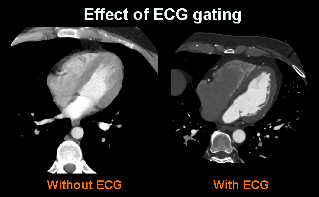
Explanation: metallic components of ECG leads may provide artifacts. However, ECG gating is essential in CTCA to reduce motion artifacts of the beating heart.
- Place an Intra venous (IV) cannula in a stable vein of the right arm – green-18G cannula.
Explanation: Green cannula has higher lumen diameter, which can withstand higher flow rates. A right arm injection is preferred in thoracic CTA because to avoid streak artifacts from undiluted contrast media in the left brachiocephalic vein.
- Practice breathing technique (arrested full inspiration) properly.
Explanation: poor breadth hold can cause motion artifacts due to diaphragm movement along with the heart.
- Explain contrast media flow sensation.
Explanation: usually, during IV contrast administration, patient may feel a burning sensation (starting from the cannulated arm and radiating downwards the trunk) and a metallic taste.
- Beta-blockers are administered under the guidance of an experienced physician.
Explanation: Beta-blocker helps to reduce the heart rate of the patient, usually, rate is kept around 50 to 70 beats per minute (bpm). Therefore, motion artifacts due to heart beat can be reduced.
- A vasodilatory drugknown as trinitroglycerin (GTN)is given sublingually (5 minutes before the image acquisition), under the guidance of an experienced physician.
Explanation: vasodilator dilates the lumen of the coronary artery, improving the visualization of atherosclerotic plaques. Blood pressure and heart rate should be monitored prior to, during and after the procedure when medications are administered.
Patient positioning
Start the patient positioning after completing patient preparation.
- Position the patient in supine and feet first on the imaging couch.
- Raise both hands above the head and place a positioning aid under them.
Explanation: hands beside the trunk give streak artifacts and increase radiation exposure.
- Keep the arm with the IV cannula strait.
Explanation: to facilitate contrast flow.
- Center the scanning area in the scanner iso-center [6].
Explanation: this reduces overall radiation exposure and increases image quality.
- Place the scout-initiation point at the level of supra sternal notch.
Scan planning
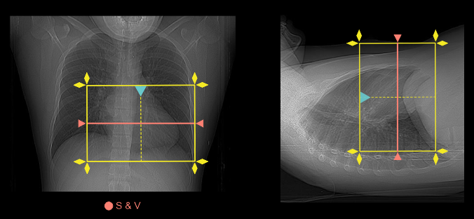
- Plan the scanning slab to cover from a point just below the carina and extending inferior to the left ventricle (volume scan).
Explanation: Coronary artery calcium scoring may be performed prior to the contrast infusion, which depends with the physician or condition of the patient.
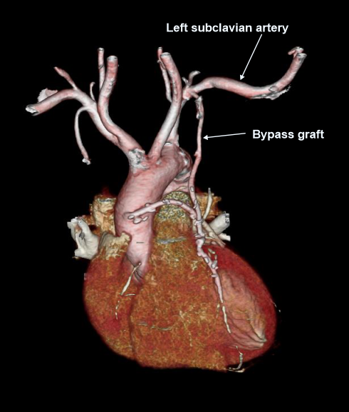
- If the patient has had previous coronary artery bypass graft (CABG) surgery, scanning slab needs to cover from the top of the clavicular heads to the apex of the heart (helical scan).
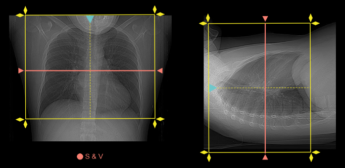
Explanation: to include bypass graftsfrom the subclavian artery to heart, and helical scan is used to cover a wide area.
- Place S & V slice in the mid part of the heart for volume scan and below carina for bypass-helical scan.
Explanation: triggering method is usually used for an on-time acquisition. Please review our Thoracic aortogram article for more detail.
- Patient’s heart rate needs to be around 50 to 70 beats per minute (bpm) for the scan.
Explanation: low heart rate gives clearer images. However, some advance scanners (640 slice) have the potential to image even with higher heart rates.
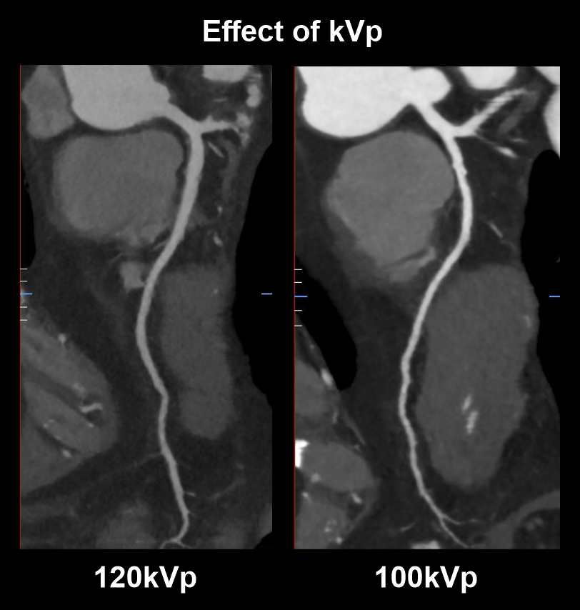
- Use 100 kVp with automated tube current modulation for patients ≤ 100 kg (non-obese).
Explanation: use of lower tube voltage (kVp) in patients with lower BMI provides satisfactory vascular contrast enhancement with slower flow rates and lower radiation dose. Although, over reduction of kVp might lead to poor image quality (high noise).
As in the diagram, scan with lower tube voltage (100kVp) has higher vascularcontrast than the scan with higher tube voltage (120kVp).
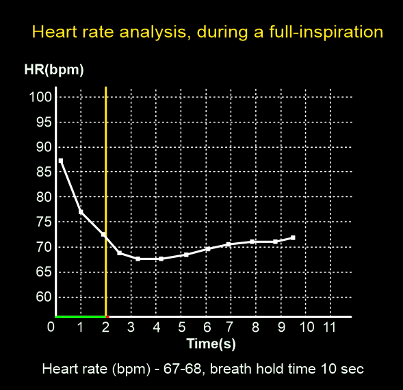
- Perform heart-rate analysis, during a full inspiration.
Explanation: image acquisition happens when the patient is under full inspiration, where the mean heart rate reduces approximately by 4 beats. This assessment is essential to select the appropriate padding and number of exposures (beats).
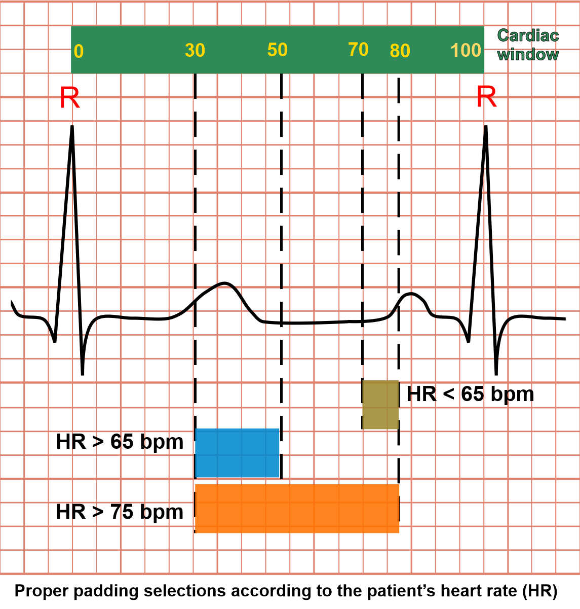
- Select suitable padding and number of exposures (beats) according to the patient’s heart rate (during full inspiration).
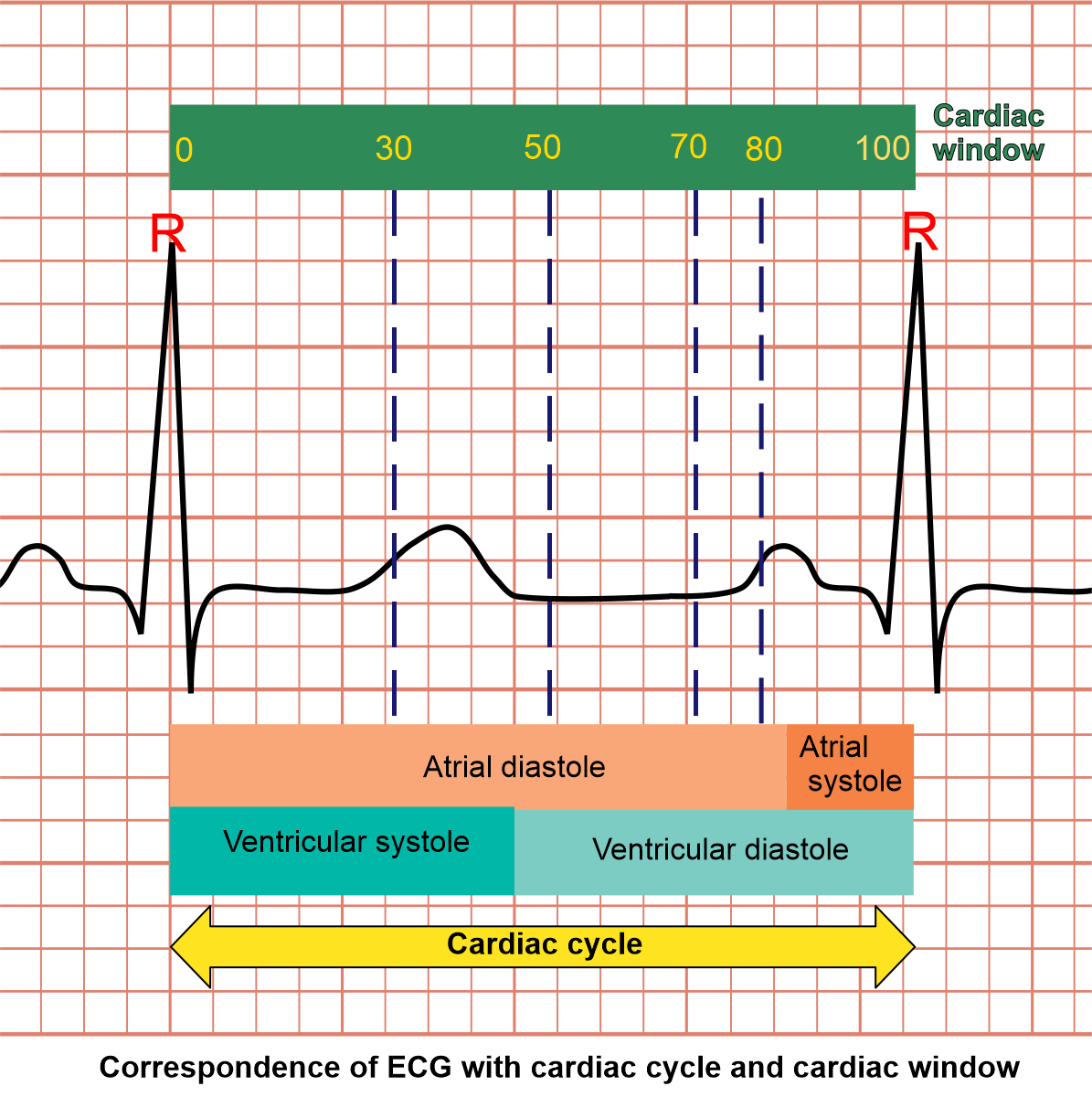
Explanations for cardiac window and gating: as we know, a cardiac cycle can be explained as the set of activities that happens between two adjacent R points (ECG). Simply, there are two major incidents in cardiac cycle which are systole and diastole. In systole, heart muscle contracts and has higher motion than diastole where it relaxes. In order to reduce motion artifacts, we usually obtain images when the heart is in it's least motion (diastolic phase).
The cardiac window is like a ruler that has numbers starting from 0 to 100, and these two ends (0 and 100) are corresponding with two-adjacent-R points (ECG). So, we’re able to select specific parts of cardiac cycle, using these numerical values. For instance, Range 70 to 80 in cardiac window represents end-diastole, and this range selection is called padding.
In CTCA imaging, patient’s heart rate (HR) is one of the major factors that defines image quality as well as radiation exposure. We can reduce the padding for a patient with a lower heart rate and may have to increase it for a higher heart rate. Although by increasing padding or number of exposures (beats), we increase the chance of capturing better images, but it also increases radiation dose.
Mentioned here are the cardiac windows according to the patient’s heart rate:
- Heart rate below 65 bpm – end diastolic (ED), 70-80%
- Heart rate over 65 bpm – end systolic (ES), 30-50%
- Heart rate over 75 bpm – end systolic (ES) to end diastolic (ED), 30-80%
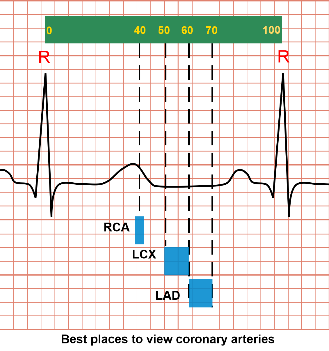
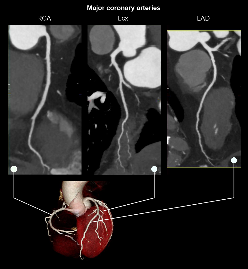
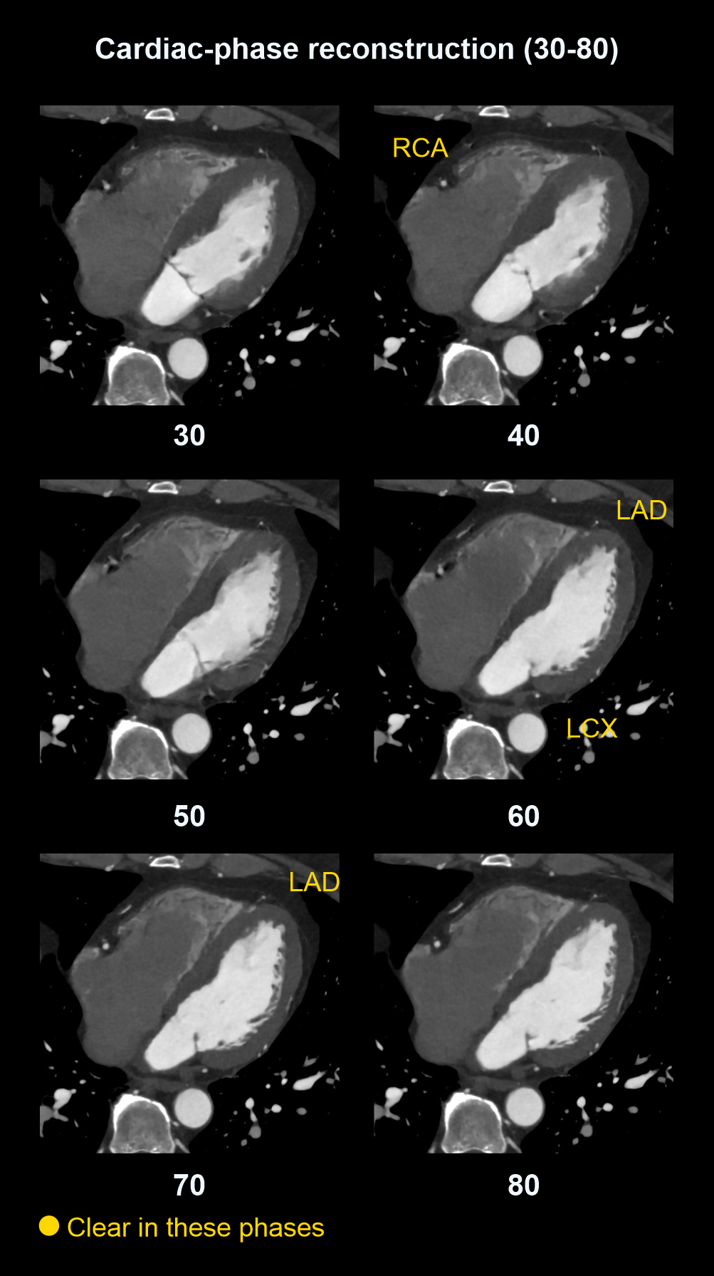
Best moments in cardiac window to view coronary arteries
Coronary arteries move during cardiac function, making them hard to image, but it seems that there are specific points in the cardiac cycle that they appear with minimal motion:
- Right coronary artery (RCA) – 40% in window
- Left anterior descending (LAD) – 60 to 70% in window
- Left circumflex artery (LCX) – 50 to 60% in window
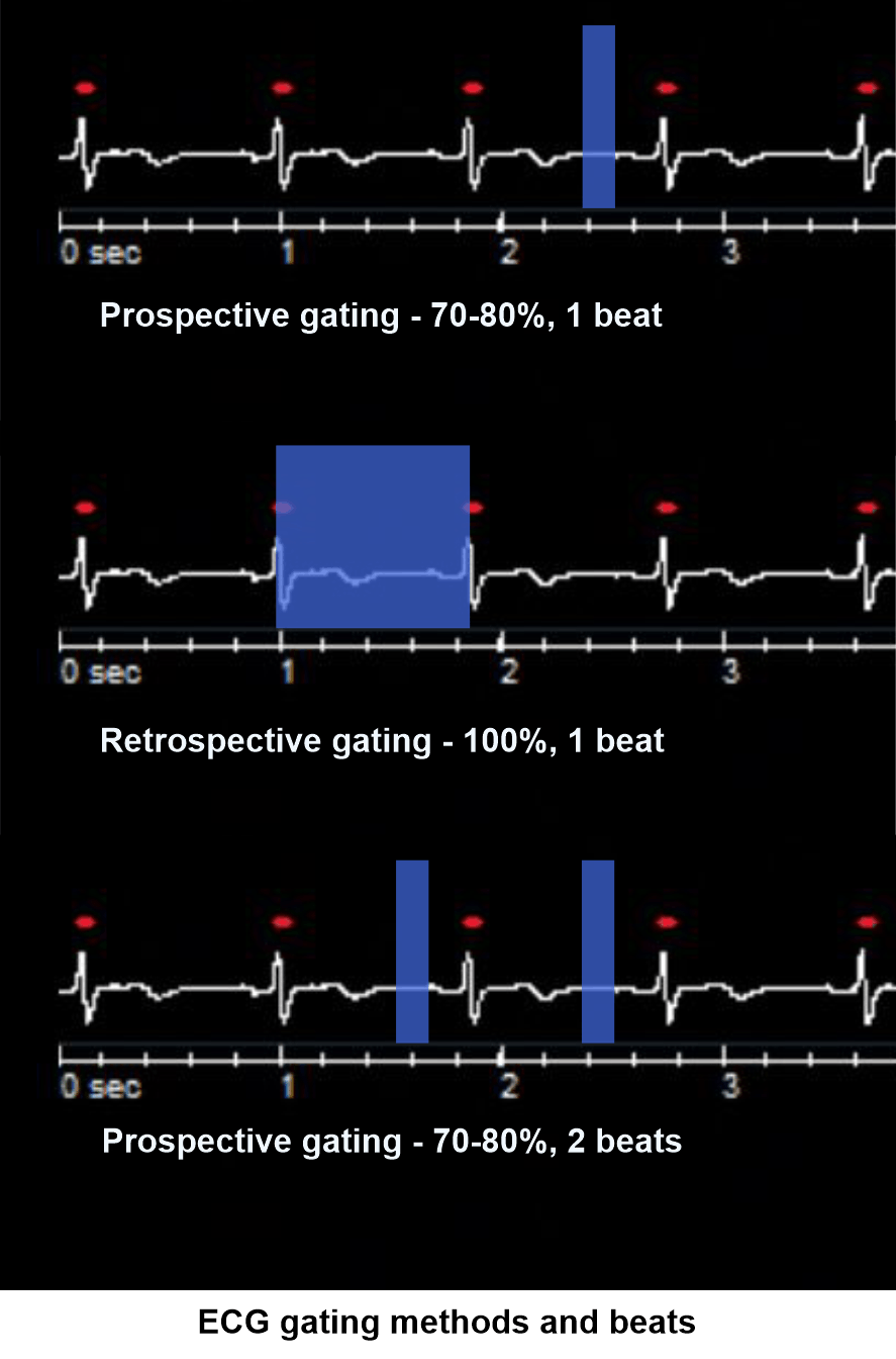
Cardiac gating
There are two major cardiac gating techniques known as prospective and retrospective. In prospective gating, a particular part of the cardiac cycle is acquired (70 to 80). In retrospective gating, whole cardiac cycle is continuously acquired (0 to 100). Comparatively, prospective gating is better as it provides lower radiation to the patient. However, for the functional analysis, whole cardiac cycle is acquired using retrospective gating.
- Triggering region of interest (ROI) is placed in the descending aorta (refer Chest contrast article for images).
- Program the threshold value to 160 HU.
- Set S & V initiation delay to 10 seconds.
- Place zero delay time for arterial scan.
Intravenous (IV) contrast infusion
- Inject iodinated contrast media at a rate of 4.5 to 7 mL/s for any patient waiting 65kg or more.
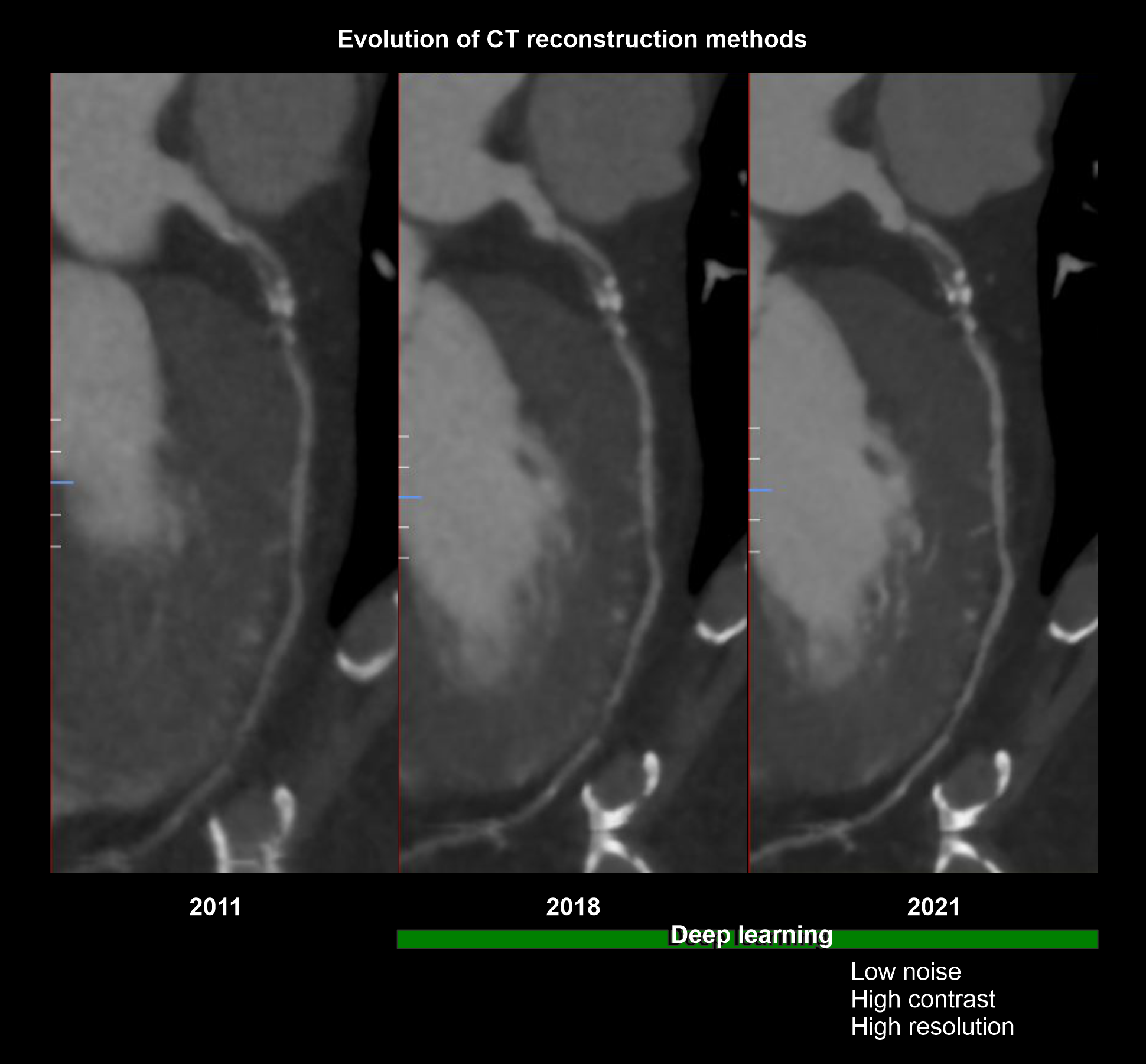
Explanation: when you plan for contrast injections, volume (mL) under flow rate (mL/s) should be nearly equal to 14 seconds or contrast volume must be injected to the patient within 14 seconds because prolonged injection may pool contrast in the right ventricle unnecessarily. Current high-tech scanners, with reconstruction methods powered by artificial intelligence (AI), has the ability to create vivid images utilizing lower contrast flow rate (4.5ml/s) and volume (65ml).
- Use nearly a 50 mL of saline flush just after completing the contrast volume.
Explanation: helps to flush out remaining contrast in veins and maintains the contrast flow for a longer time.
- For Helical bypass graft scans, add an extra 10 mL to the usual contrast volume.
Explanation: In bypass graft study, scan coverage is comparatively wider than the routine scan, and requires higher contrast volume.
Post-processing
For coronary artery evaluation:
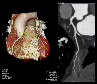
- Curved planner reformations (CPRs) of coronary arteries.
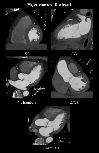
- 2D views of the heart or multiplanar reformations (MPRs): four chambers, three chambers, left ventricular outflow track (LVOT), short axis (SA) and vertical long axis (VLA).
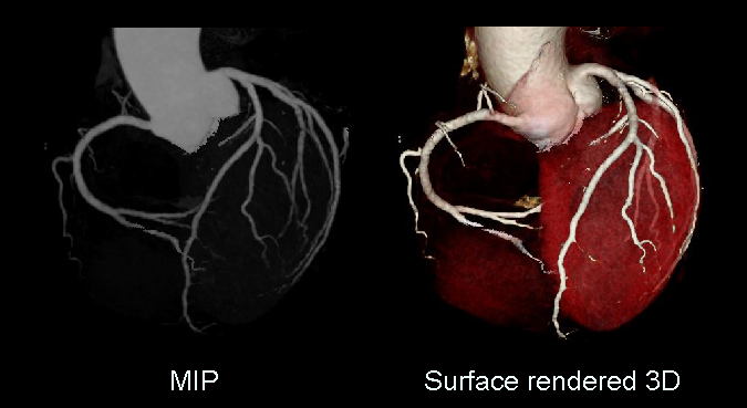
- 3D reconstructed and maximum intensity projection images.
- 4D dynamic reconstructions.
For retrospective and wide prospective acquisitions (30-80%), images should be reconstructed at various phases of cardiac cycle. Usually, a 10% gap is kept between each phase separation. For instance, images are reconstructed as 0, 10, 20, 30, 40, 50, 60, 70, 80, 90 and 100 for a retrospective (100%) acquisition.
For non-cardiac structures evaluation:
- Axial images in both lung and soft tissue windows at ≤ 5-3mm slice thickness.
Reference
- Takx, R. A., Suchá, D., Park, J., Leiner, T., & Hoffmann, U. (2015). Sublingual Nitroglycerin Administration in Coronary Computed Tomography Angiography: a Systematic Review.European radiology, 25(12), 3536– 3542. https://doi.org/10.1007/s00330-015-3791-3
- Zhang, J., Fletcher, J. G., Scott Harmsen, W., Araoz, P. A., Williamson, E. E., Primak, A. N., & McCollough, C. H. (2008). Analysis of heart rate and heart rate variation during cardiac CT examinations.Academic radiology, 15(1), 40–48. https://doi.org/10.1016/j.acra.2007.07.023
- Hedgire, S. S., Baliyan, V., Ghoshhajra, B. B., & Kalra, M. K. (2017). Recent advances in cardiac computed tomography dose reduction strategies: a review of scientific evidence and technical developments.Journal of medical imaging (Bellingham, Wash.), 4(3), 031211. https://doi.org/10.1117/1.JMI.4.3.031211
- Larissa Braga Casaburi, MD, MPH, MHA, Co-Chair, Andrew L. Rivard, MD, Co-Chair, & Dhiraj Baruah, MD. (2022). ACR–NASCI–SPR Practice parameter for the performance of quantification of cardiovascular computed tomography (CT) and magnetic resonance imaging (MRI).Retrieved from www.gravitas.acr.org.
- Klaus Hagspiel, MD, Chair, Lucia Flors Blasco, MD, PhD, & Cristina Fuss, MD. (2021). ACR–NASCI–SPR Practice parameter for the performance and interpretation of cardiac computed tomography (CT).Retrieved from www.gravitas.acr.org.
- Romanyukha, A., Nzitunga, P. S., & Dolcet, A. (2022, April 28). CT patient positioning plays key role in radiation dose reduction.www.auntminnie.com.
- Desjardins B, Kazerooni EA. ECG-gated cardiac CT.AJR Am J Roentgenol. 2004 Apr;182(4):993-1010. doi: 10.2214/ajr.182.4.1820993. PMID: 15039178.
- Mander, G. T. W., Dobeli, K., Steffensen, C., & Munn, Z. (2021). Diagnostic accuracy of prospectively gated, 128-slice or greater CTCA at high heart rates: a systematic review and meta-analysis.Journal of medical radiation sciences, 68(4), 435–445. https://doi.org/10.1002/jmrs.525
- Qin, J., Liu, L. Y., Fang, Y., Zhu, J. M., Wu, Z., Zhu, K. S., Zhang, J. S., & Shan, H. (2012). 320-detector CT coronary angiography with prospective and retrospective electrocardiogram gating in a single heartbeat: comparison of image quality and radiation dose. The British journal of radiology, 85(1015), 945–951. https://doi.org/10.1259/bjr/29901700
- Prof. Mickaël Ohana, & Dr. Fuminari Tatsugami. (2025, January 18). Precise IQ Engine.Retrieved from www.global.medical.canon.